Also known as:
Type SE, Style SER and SEU Service Entrance Cable;
Copper Aluminum Service Entrance (SE) Cable;
Ground service entrance cable;
SEU: Service Entrance cable, Unarmored;
SER: Service Entrance cable with Reinforcement tape;
APPLICATIONS OF AL/CU Service Entrance (SE) Cable
service entrance cable is used to convey power from the service drop to the meter base and from the meter base to the distribution panelboard; however, it may be used in all applications where Type SE cable is permitted. SE SER may be used in wet or dry above ground locations at temperatures not to exceed 90°C. The voltage rating is 600 volts.
CONSTRUCTION:
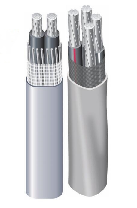
Type SE cable is constructed with AA-8000 series aluminum alloy, compacted stranded conductors. The conductors are covered with a sunlight resistant Type XHHW-2 or TypeTHHN/THWN-2-insulation.
A reinforcement tape is wrapped around the conductors for added strength and conformity. A gray sunlight-resistant polyvinyl chloride (PVC) outer jacket covers the entire assembly.
Style SEU cable has two phase conductors surrounded by a concentric neutral while the SER style has two, three or four phase conductors and a bare neutral.
Style SER Cable’s phase conductors are identified by a colored stripe on the insulation.
3 conductor – Black and Black with Red Stripe
4 conductor – Black, Black with White Stripe and Black with Red Stripe
5 conductor – Black, Black with White Stripe, Black with Red Stripe and Black with Blue Stripe
Standards:
ASTM- B-800 and B-801
UL Standard 44 for XHHW-2
UL Standard 83 for THHN/THWN-2
Federal Specification A-A-59544
National Electrical Code, NFPA 70, 2011 Edition
RoHS
CONSTRUCTION:
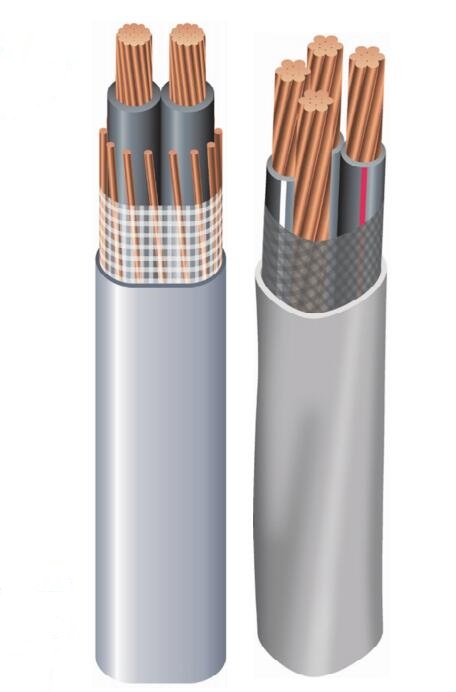
Type SE cable is constructed with sunlight resistant Type XHHW-2 conductors or Type THHN/THWN conductors.
Copper conductors are annealed (soft) copper. Cable assembly plus reinforcement tape are jacketed with sunlight resistant gray polyvinyl chloride (PVC).
Available as 1 conductor with a concentric ground, 2 conductor with a round or concentric ground, or 3 conductor with a bare ground. SE cable is jacketed with gray sunlight resistant polyvinyl chloride (PVC).
Standards:
ASTM- All applicable standards
UL Standard 44 for XHHW-2 conductors
UL Standard 83 for THHN/THWN conductors
UL Standard 854
Federal Specification A-A-59544
National Electrical Code, NFPA 70. 2011 Edition
RoHS/ REACH
Aluminum Service Entrance (SE) Cable
| Aluminum Service Entrance (SE) Cable | |||||||||
| Conductor | Stranding | Nominal O.D. (Mils) | Allowable Ampacities | Approximate Net Weight Per 1000′ (Lbs) | Standard Package | ||||
| Size/Const. AWG or kcmil | Phase Conductor & Neutral | Equipment Ground Conductor | 60°C | 75°C | 90°C | Dwelling | |||
| SER Aluminum Two-Conductor With Bare Ground (Formerly referred to as “EZ-SE”) | |||||||||
| 6-6-6 | 7 | – | 650 | 40 | 50 | 60 | – | 150 | B |
| 4-4-4 | 7 | – | 745 | 55 | 65 | 75 | – | 203 | B |
| 4-4-6 | 7 | – | 745 | 55 | 65 | 75 | – | 203 | B |
| 2-2-2 | 7 | – | 864 | 75 | 90 | 100 | 100 | 290 | B |
| SER Aluminum Three Conductor With Bare Ground (Formerly referred to as “Four Conductor”) | |||||||||
| 8-8-8-8 | 1 | 1 | 612 | 30 | 40 | 45 | – | 136 | B |
| 6-6-6-6 | 7 | 7 | 717 | 40 | 50 | 60 | – | 196 | B |
| 4-4-4-6 | 7 | 7 | 823 | 55 | 65 | 75 | – | 252 | B |
| 2-2-2-4 | 7 | 7 | 956 | 75 | 90 | 100 | 100 | 359 | B |
| 1-1-1-3 | 8 | 7 | 1079 | 85 | 100 | 115 | 110 | 449 | C |
| 1/0-1/0-1/0-2 | 10 | 1 | 1168 | 100 | 120 | 135 | 125 | 540 | C |
| 2/0-2/0-2/0-1 | 12 | 1 | 1264 | 115 | 135 | 150 | 150 | 652 | C |
| 3/0-3/0-3/0-1/0 | 16 | 1 | 1371 | 130 | 155 | 175 | 175 | 786 | C |
| 4/0-4/0-4/0-2/0 | 19 | 1 | 1496 | 150 | 180 | 205 | 200 | 960 | C |
| 250-250-250-3/0 | 22 | 1 | 1839 | 170 | 205 | 230 | 225 | 1458 | C |
| SER Aluminum Four Conductor With Bare Ground (Formerly referred to as “Five Conductor”) | |||||||||
| 2-2-2-2-4 | 6 | 7 | 1059 | 75 | 90 | 100 | 100 | 452 | B |
| 2/0-2/0-2/0-2/0-1 | 12 | 1 | 1404 | 115 | 135 | 150 | 150 | 827 | C |
| 4/0-4/0-4/0-4/0-2/0 | 19 | 1 | 1672 | 150 | 180 | 205 | 200 | 1228 | C |
| 250-250-250-250-3/0 | 22 | 1 | 1847 | 170 | 205 | 230 | 225 | C | |
| Conductor | Stranding | Nominal O.D. (Mils) | Allowable Ampacities | Approximate Net Weight Per 1000′ (Lbs) | Standard Package | ||||
| Phase Conductor & Neutral | Equipment Ground Conductor | 60°C | 75°C | 90°C | Dwelling | ||||
| Size/Const. AWG or kcmil | |||||||||
| SEU Aluminum Two Conductor With Bare Conentric Ground (Formerly referred to as “Three Conductor”) | |||||||||
| 6-6-6 | 7 | 8 | 430×687 | 40 | 50 | 60 | – | 145 | B,C,E |
| 4-4-4 | 7 | 12 | 499×800 | 55 | 65 | 75 | – | 198 | B |
| 4-4-6 | 7 | 15 | 474×775 | 55 | 65 | 75 | – | 181 | B |
| 2-2-2 | 7 | 14 | 569×925 | 75 | 90 | 100 | 100 | 283 | B,C,G |
| 2-2-4 | 7 | 18 | 554×910 | 75 | 90 | 100 | 100 | 259 | B,C,G |
| 2/0-2/0-2/0 | 18 | 18 | 736×1221 | 115 | 135 | 150 | 150 | 514 | C |
| 2/0-2/0-1 | 18 | 14 | 720×1205 | 115 | 135 | 150 | 150 | 468 | C |
| 4/0-4/0-4/0 | 18 | 18 | 878×1462 | 150 | 180 | 205 | 205 | 765 | C |
| 4/0-4/0-2/0 | 18 | 18 | 835×1419 | 150 | 180 | 205 | 205 | 691 | C |
| Table values reflect XHHW-2 conductors. Allowable ampacities shown are for general use as specified by the National Electrical Code, 2011 Edition, Section 310.15. | |||||||||
| 60°C – When terminated to equipment for circuits rated 100 amperes or less or marked for 14 through 1 AWG conductors. See NEC Article 338.10 (B)(4). | |||||||||
| 75°C – When terminated to equipment for circuits rated 100 amperes or marked for conductors larger than 1 AWG conductors. | Package Codes: B – 1,000′ C- 500′ E-250′ G-200′ | ||||||||
| May not apply, see NEC Article 338.10 (B)(4). | |||||||||
| 90°C – Wet or dry locations. For ampacity de-rating purposes. | |||||||||
| Dwelling – For units, conductors shall be permitted at listed ampacities as 120/240-volt, 3-wire, single-phase services and feeders per NEC Article 310.15. | |||||||||
| *For compact-stranded construction, the number of wires, as permitted by UL Standard 854 and ASTM B-801 may be reduced as follows: 19-wire constructions – 18 wires minimum. | |||||||||
Copper Service Entrance (SE) Cable
| Conductor | Stranding | Nominal O.D. (Mils) | Allowable Ampacities | Approximat e Net Weight Per 1000′ (Lbs) | Standard Package | ||||
| 60°C | 75°C | 90°C | Dwelling | ||||||
| Phase Conductor & Neutral | Equipment Ground Conductor | ||||||||
| Size/Const. AWG or kcmil | |||||||||
| SER Two Conductor With Bare Contentric Ground (Formerly referred to as “Three Conductor”) | |||||||||
| 8-8-8 | 7 | — | 586 | 40 | 50 | 55 | — | 231 | B |
| 6-6-6 | 7 | — | 669 | 55 | 65 | 75 | — | 338 | B |
| 4-4-4 | 7 | — | 764 | 70 | 85 | 95 | 100 | 498 | B |
| 3-3-3 | 7 | — | 829 | 85 | 100 | 110 | 110 | 611 | B |
| 2-2-2 | 7 | — | 896 | 95 | 115 | 130 | 125 | 752 | B |
| 1-1-1 | 19 | — | 1021 | 110 | 130 | 150 | 150 | 948 | C |
| 1/0-1/0-1/0 | 19 | — | 1114 | 125 | 150 | 170 | 175 | 1169 | C |
| 2/0-2/0-2/0 | 19 | — | 1209 | 145 | 175 | 195 | 200 | 1444 | C |
| 3/0-3/0-3/0 | 19 | — | 1317 | 165 | 200 | 225 | 225 | 1792 | C |
| 4/0-4/0-4/0 | 19 | — | 1438 | 195 | 230 | 260 | 250 | 2226 | C |
| SER Three Conductor With Bare Ground (Formerly referred to as “Four Conductor”) | |||||||||
| 8-8-8-8 | 7 | 7 | 645 | 40 | 50 | 55 | — | 286 | B |
| 6-6-6-6 | 7 | 7 | 738 | 55 | 65 | 75 | — | 424 | B |
| 4-4-4-6 | 7 | 7 | 844 | 70 | 85 | 95 | 100 | 585 | B |
| 3-3-3-5 | 7 | 7 | 910 | 85 | 100 | 110 | 110 | 719 | B |
| 2-2-2-4 | 7 | 7 | 984 | 95 | 115 | 130 | 125 | 887 | B |
| 1-1-1-3 | 19 | 7 | 1132 | 110 | 130 | 150 | 150 | 1117 | C |
| 1/0-1/0-1/0-2 | 19 | 19 | 1235 | 125 | 150 | 170 | 175 | 1382 | C |
| 2/0-2/0-2/0-1 | 19 | 19 | 1342 | 145 | 175 | 195 | 200 | 1713 | C |
| 3/0-3/0-3/0-1/0 | 19 | 19 | 1462 | 165 | 200 | 225 | 225 | 2129 | C |
| 4/0-4/0-4/0-2/0 | 19 | 19 | 1598 | 195 | 230 | 260 | 250 | 2650 | C |
| Table values reflect XHHW-2 conductors | Package Code: A-250′ B-500′ C-1,000′ D-100 E- 150′ | ||||||||
| Allowable ampacities shown are for general use as specified by the National Electrical Code, 2011 Edition, section 310.15 and 240.4(D). | |||||||||
| Unless the is marked for use at higher temperatures the conductor ampacities shall be limited to the following per NEC 110.14(C) | |||||||||
| 60 °C When terminated to equipment for circuits rated 100 amperes or less or marked for 14 – 1 AWG conductors. | |||||||||
| 75 °C When terminated to equipment for circuits rated over 100 amperes or marked for conductors larger than 1 AWG. | |||||||||
| 90 °C XHHW wet or Dry locations for ampacity adjustment purposes using NEC section 310.15 For dwelling ampacity use section 310.15(B)(7) | |||||||||
| Conductor | Stranding | Nominal O.D. (Mils) | Allowable Ampacities | Approximate Net Weight Per 1000′(Lbs) | Standard Package | ||||
| Size/Const. AWG or kcmil | Phase Conductor & Neutral | Equipment Ground Conductor | 60°C | 75°C | 90°C | Dwelling | |||
| SEU Two Conductor With Bare Concentric Ground (Formerly referred to as “Three Conductor”) | |||||||||
| 10-10-10 | 1 | 12 | 428 X 283 | 30 | 30 | 30 | — | 127 | ABC |
| 8-8-8 | 7 | 8 | 587 X 380 | 40 | 50 | 60 | — | 211 | ABC |
| 6-6-6 | 7 | 12 | 659 X 416 | 55 | 65 | 75 | — | 308 | BCE |
| 4-4-4 | 7 | 12 | 815 X 506 | 70 | 85 | 95 | 100 | 471 | BCE |
| 3-3-3 | 7 | 12 | 883 X 548 | 85 | 100 | 110 | 110 | 583 | B |
| 2-2-2 | 7 | 15 | 994 X 578 | 95 | 115 | 130 | 125 | 718 | BD |
| 1-1-1 | 19 | 14 | 1093 X 664 | 110 | 130 | 150 | 150 | 904 | B |
| 1/0-1/0-1/0 | 19 | 18 | 1179 X 707 | 125 | 150 | 170 | 175 | 1123 | BC |
| 2/0-2/0-2/0 | 19 | 18 | 1283 X 767 | 145 | 175 | 195 | 200 | 1379 | BC |
| 3/0-3/0-3/0 | 19 | 14 | 1429 X 862 | 165 | 200 | 225 | 225 | 1712 | BD |
| 4/0-4/0-4/0 | 19 | 18 | 1541 X 918 | 195 | 230 | 260 | 250 | 2146 | BC |
| SEU Two Conductor With Bare Concentric Ground (Formerly referred to as “Three Conductor”) (Reduced Neutral) | |||||||||
| 6-6-8 | 7 | 8 | 659 X 416 | 55 | 65 | 75 | — | 281 | BC |
| 4-4-6 | 7 | 12 | 790 X 481 | 70 | 85 | 95 | 100 | 420 | BC |
| 3-3-5 | 7 | 15 | 843 X 508 | 85 | 100 | 110 | 110 | 515 | BC |
| 2-2-4 | 7 | 12 | 929 X 563 | 95 | 115 | 130 | 125 | 639 | BC |
| Table values reflect XHHW-2 conductors | Package Code: A-250’B-500′ C-1,000′ D-100’E- 150′ | ||||||||
| Allowable ampacities shown are for general use as specified by the National Electrical Code, 2011 Edition, section 310.15 and 240.4(D). | |||||||||
| Unless the is marked for use at higher temperatures the conductor ampacities shall be limited to the following per NEC 110.14(C) | |||||||||
| 60 °C When terminated to equipment for circuits rated 100 amperes or less or marked for 14 – 1 AWG conductors. | |||||||||
| 75 °C When terminated to equipment for circuits rated over 100 amperes or marked for conductors larger than 1 AWG. | |||||||||
| 90 °C XHHW wet or Dry locations for ampacity adjustment purposes using NEC section 310.15 For dwelling ampacity use section 310.15(B)(7) | |||||||||
HUADONG CABLE GROUP SINCE 1999
Professional Cables and Wires Manufacturer in China
We can design cables according to your requirement


Verified Manufacturer

